How is the Frequency Divided?
In one of the previous articles, we made an application about the 74393 counter. Counter Application with 74HC393 - Electronics World News (milivolt.news)
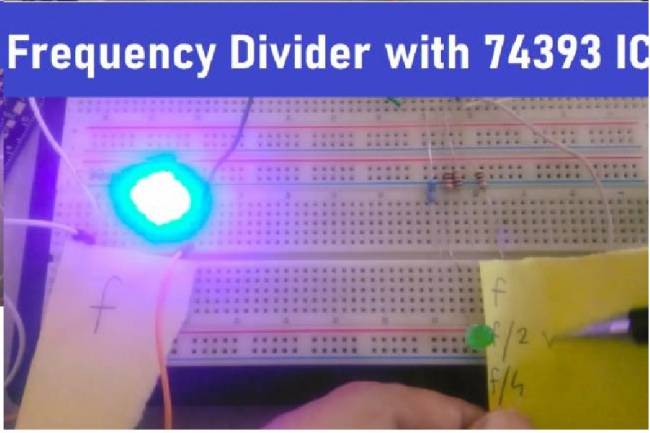
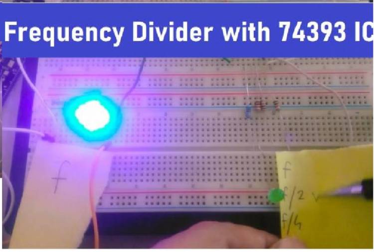
You can find the circuit we made on the breadboard on our youtube channel.
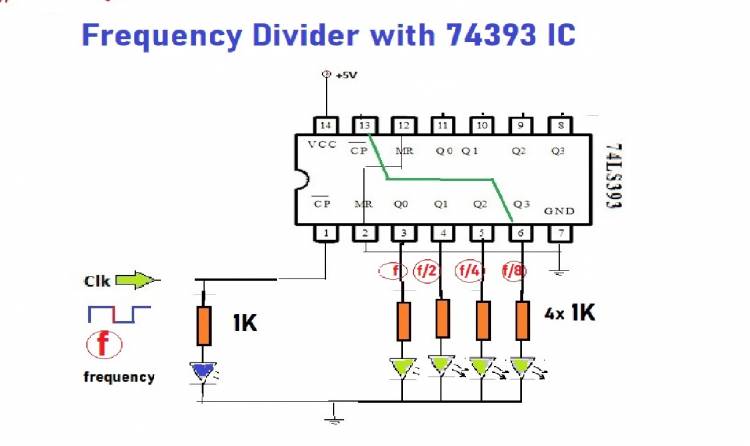
We connected the square wave output of the signal generator to the 1st clock of the 74393 IC. When we clocked at the “f” frequency, the outputs of the counter were increasing binary. Binary increments correspond to increments of numbers in the decimal number system. 0,1,2,3,4,5…
Digital outputs also mean something else: each decimal number actually means the frequency applied to the input divided by that number. At the output of the counter, a signal of frequency f/2 is actually generated. A signal with frequency f/4 occurs at output Q2, and a signal with frequency f/8 occurs at output Q3. Q0 continues to generate signals at frequency f.
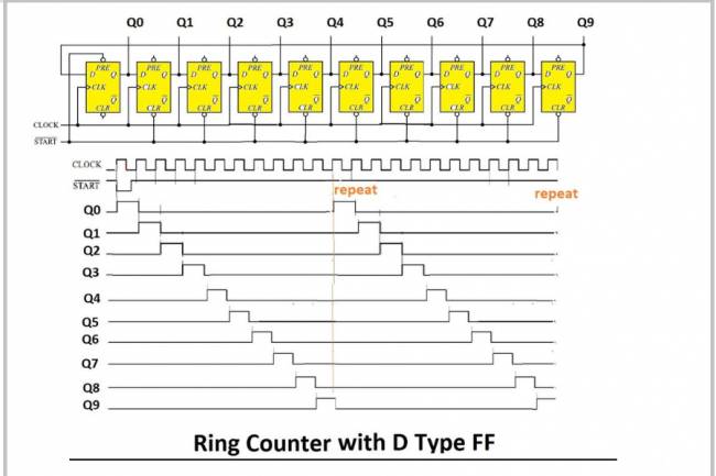
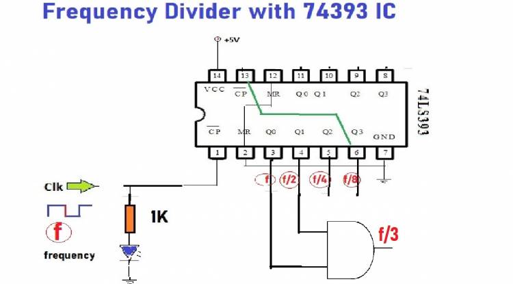
If we want to obtain a signal at a different frequency; For example, if we want to obtain a signal at f/3 frequency, it is sufficient to connect the Q0 and Q1 outputs to an AND gate logic gate as seen in the picture below. Because when Q0 and Q1 outputs are "1", AND logic gate output is also "1". The outputs of Q0 and Q1 being “1” in the decimal number system corresponds to the number 3 in the decimal system.
Especially in digital electronic circuits, very different signal frequencies may be required. We can obtain multiple frequency ends using a single 74393 IC.