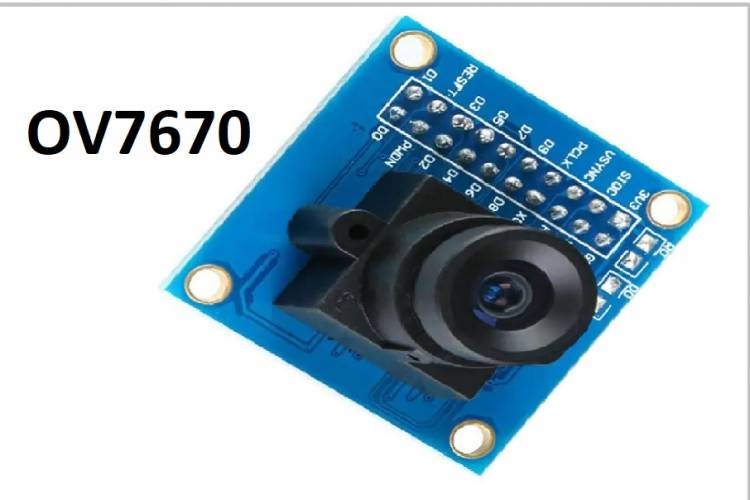
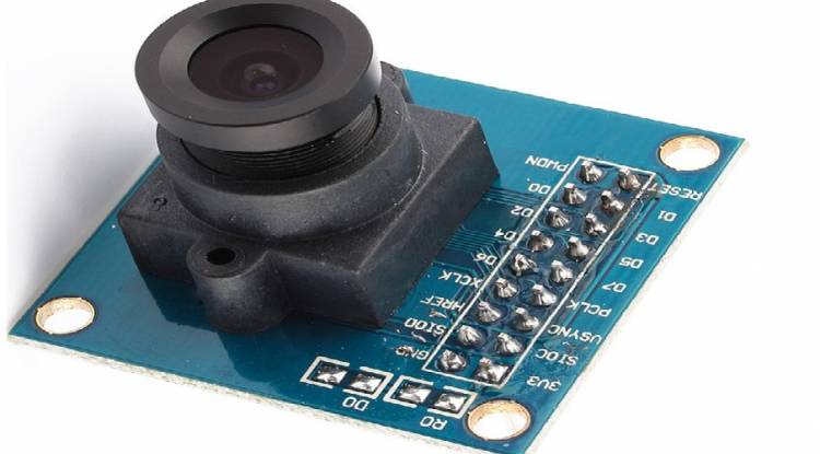
OV7670 CMOS VGA MODULE
The OV7670 is a CMOS (Complementary Metal-Oxide-Semiconductor) image sensor and is frequently used in embedded systems, development platforms such as Arduino, or other projects.
Some technical information about the OV7670:
1. Resolution: OV7670 is a sensor with VGA (640x480) resolution. It may have different resolution modes, but VGA mode is the most commonly used.
2. Color Support: OV7670 can capture color images and produces data mostly in RGB format.
3. Interface: The sensor can use communication protocols such as I2C or SCCB (Serial Camera Control Bus) for data reading and control operations.
4. Sample Rate: The OV7670 can be set to different sample rates, providing a balance between image quality and speed.
5. Image Processing Features: The OV7670 may have some image processing features, but these functions may vary from model to model.
6. Lens: Usually the sensor is combined with a lens and the quality of this lens affects the image quality.
7. Uses: OV7670 is used for many applications that require image capture. For example, this sensor can be used in a variety of projects such as image processing projects, camera modules, and robotic applications.
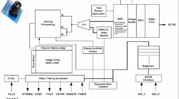
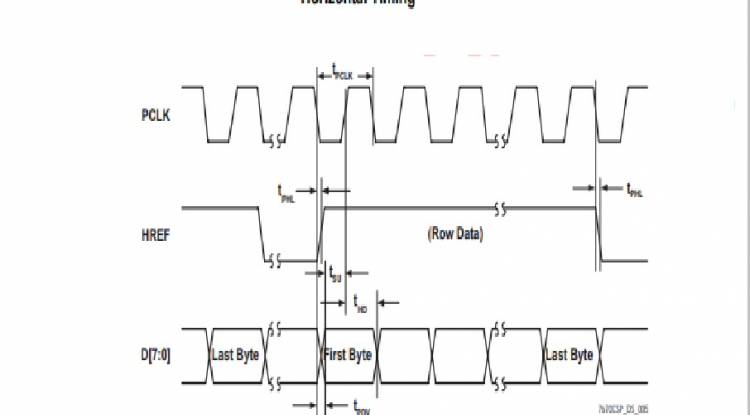
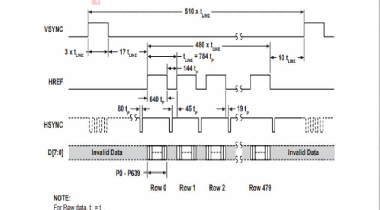
OV7670 Timing
Common pin structures of the OV7670 camera module are as follows:
1. VCC: It is the supply voltage pin of the sensor (usually 3.3V or 5V).
2. GND: Ground connection pin.
3. SIOC (Serial Camera Interface Clock): Clock signal for I2C or SCCB communication.
4. SIOD (Serial Camera Interface Data): Data line for I2C or SCCB communication.
5. RESET: It is the reset pin of the sensor. This pin is used to initialize or reset the sensor.
6. XCLK (External Clock): A pin that works synchronously with an external clock signal. This pin is used to control the operating speed of the sensor.
7. PWDN (Power Down): Used to put the sensor into sleep mode or reactivate it.
8. VSYNC (Vertical Synchronization): The vertical synchronization signal determines the beginning of the image scan.
9. HREF (Horizontal Reference): Reference signal for the horizontal scan line.
10. D[7:0] (Data Bus): 8 data pins that carry image data. Data about image pixels is transmitted with these pins.
11. SCL and SDA: Two pins used for I2C or SCCB communication.
12. AVDD and DVDD: Analog and digital supply voltage pins provide power to different modules of the sensor.
13. AGND and DGND: Analog and digital ground connections.
Datasheets: OV7670_DS (1.4).fm (mit.edu)