Function Signal Generator Operation
The signal generator is one of the must-have devices in an electronics workshop. Low frequency, mid frequency and high frequency sources should be available in every electronics workshop.
There are many integrated circuit-chip(IC) available for signal generator in the market. In addition to these, we can also make a signal generator using logic gates and other electronic materials. We often prefer ICs built for signal generator-only duty because they have high signal stability.
Assembly and test application is available on our youtube channel.
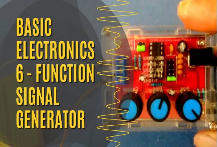
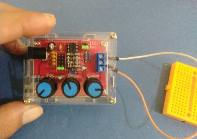
A quality signal is also sought in low-frequency signals. For this, we will use a pre-assembled device using the XR-2206 chip.
The XR-2206 is a monolithic function signal generator. It can generate high quality sinusoidal, square, triangle, ramp and pulse waveforms with high stability and accuracy.
The frequency range is between 0.01 Hz-1MHz. It can also be modulated with an external signal.
Usage areas :
Sweep generation, AM/FM applications, V/F conversions, FSK generation, VCO applications.
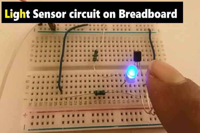
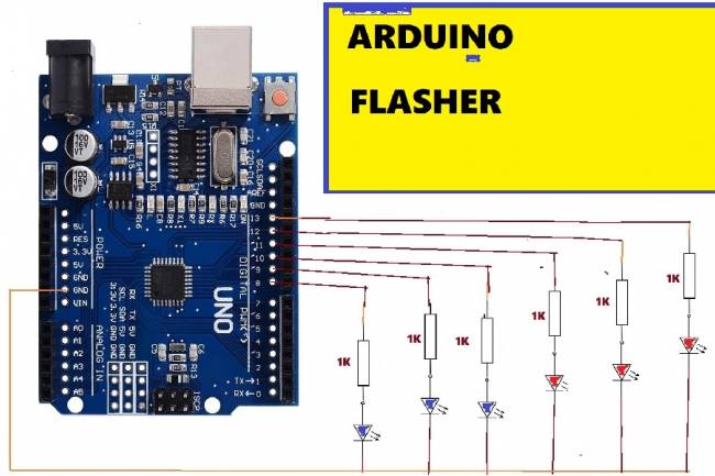
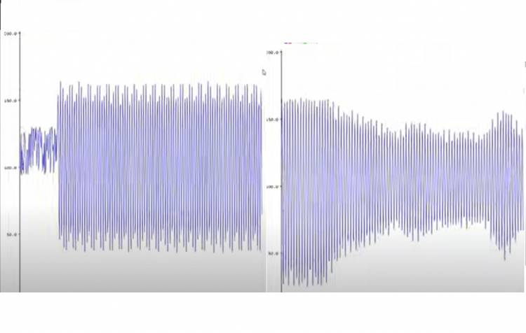
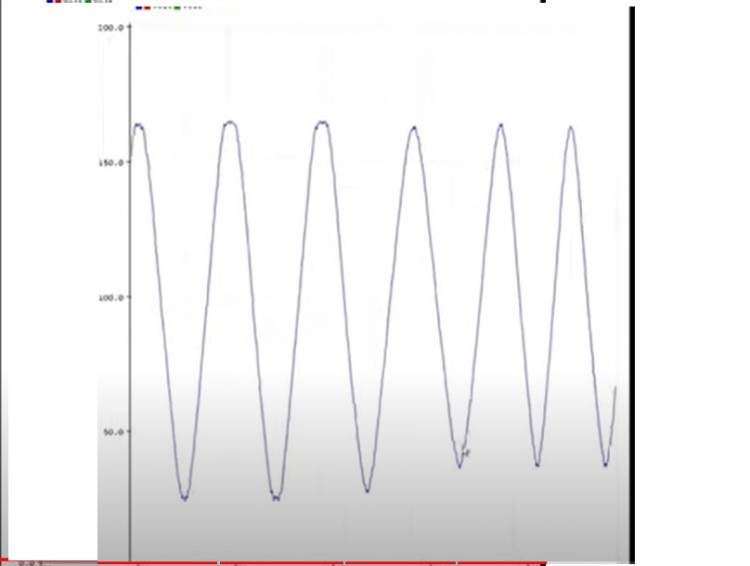
The installation of the device that we will assemble and test is very easy. The test was done with a led and then with a microcontroller/Arduino Analog input. When we click on Arduino Tools---serial plotter, we will see sine wave, square wave and sawtooth waveforms in the graphical interface.
Arduino Codes: