How to make a precision Signal Generator?
If we want to design a signal generator for use in electronics laboratories and workshops, one of the best ways is to use the ICL8038 IC.
In our previous application, we obtained a square wave using the NE555 timer IC. We tried to get saw wave signal and sine wave signal by connecting RC circuits to square wave output end.
We used much more elements than the ICL8038 chip to get three different signals with the NE555. The most important advantage of the ICL8038 chip is to obtain three signal shapes simultaneously with very few circuit elements. In addition, the signal patterns are very clean and the signal noise is very low. In the ICL8038 information pages, the frequency shift change characteristic depending on the temperature is given as follows:
Low Frequency Slip with Temperature. . . . . . .250ppm/oC ,
Low Distortion. . . . . . . . . . . . . . . . 1% (Sine Wave Output)
• High Linearity . . . . . . . . . . . 0.1% (Triangular Wave Output)
The ICL8038 has a very wide frequency range. Square, triangle-saw and sine wave signals can be generated in the frequency range of 0.001Hz - 300kHz.
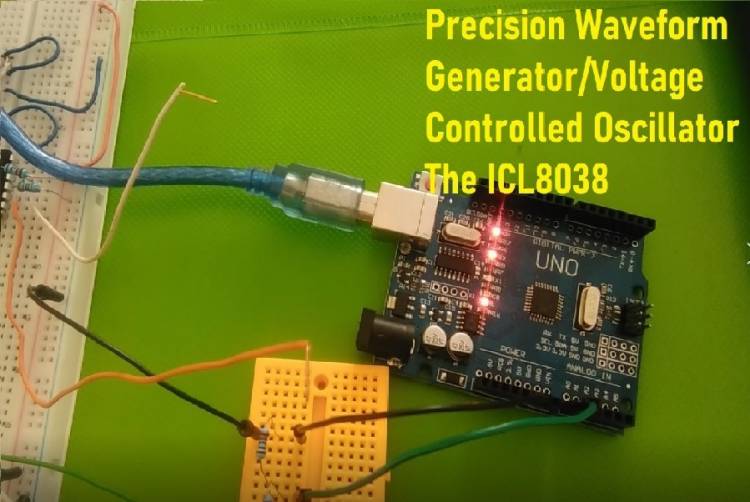
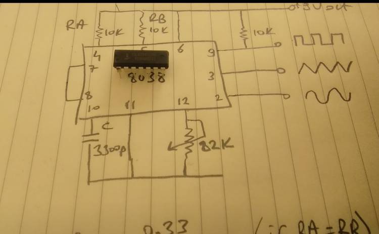
We found the test circuit of the signal generator from the manufacturer's information pages. We installed it on the BreadBoard.
Normally this chip also works with symmetrical power supplies. So for example; It works with +12 volt -12 volt symmetrical power supply. We used a 9 Volt battery in the experimental circuit.
We used the analog input (A0) of the microcontroller to see the output signals. We checked the waveforms on the graphical display with Tools-Serial Plotter.
In the circuit we tested, the frequency calculation was made with the following formula:
F=0.33/CxR. This formula is valid provided that the resistances RA and RB are equal.