Making a Signal Generator with LM555
LM555, in electronics laboratories; It is an IC that is widely used in small signal applications and digital electronics applications. It can generate stable signal up to 1MHz. With the LM555, which is used as a square wave generator, many circuits can be made with a few circuit elements.
The way the LM555 chip works is as follows: there is an RS Flip Flop inside the chip. RS flip flop is a common flip flop used in digital electronics. It has two entrances. When the logical state of the Reset and Set inputs changes, the output also changes. Resistors and capacitors connected to other pins of the chip determine the status of Reset and Set inputs.
The charging and discharging times of these resistors and capacitors may differ. Due to this difference, the output square waveform of the chip may change. As we can obtain a square wave with a fixed frequency, we can also obtain waves whose frequency changes per unit time. For example, we can obtain a PWM waveform and by connecting this signal to a DC motor, we can control the speed of the motor.
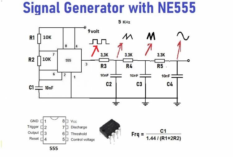
In the signal generator application, we get a fixed frequency wave from output pin 3 of the LM555. We obtain a 5KHz signal with the help of resistors R1, R2 and capacitor C1. We can use this square wave signal in any circuit input we want.
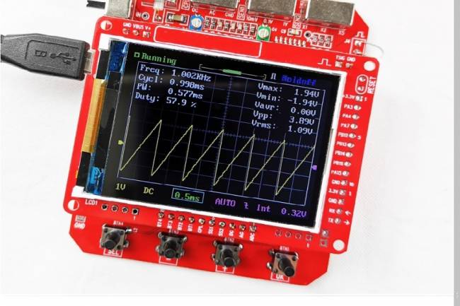
If we connect RC circuits to output 3 of the LM555, respectively, the square wave signal will first turn into saw waveform and finally sine waveform.
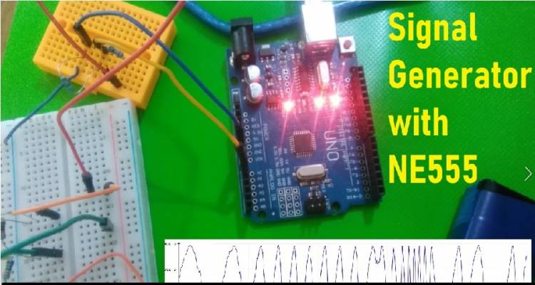
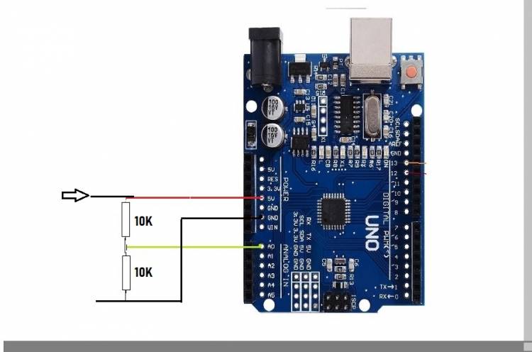
In the circuit we built on the breadboard, we connected the signal from the last RC stage to the analog input terminal of the Arduino microcontroller with a voltage divider. We received the signal with the Arduino input command AnalogRead and observed the waveform at the output of the "Serial Plotter". With a small margin of error, we got a 5KHz sine wave signal.
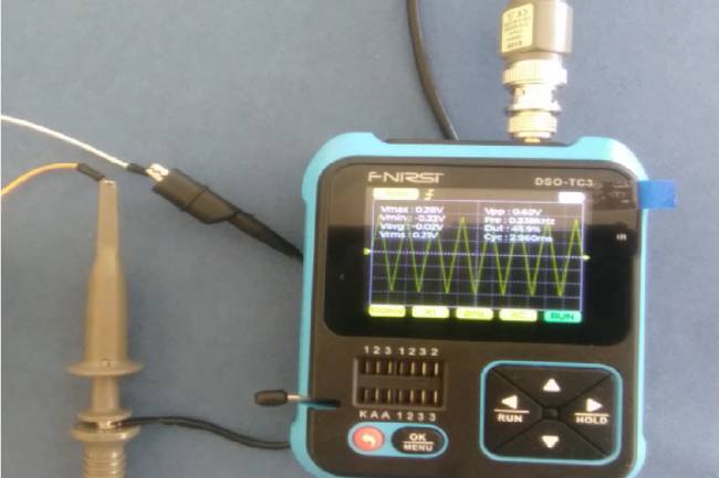
If we want to use a saw wave signal, we must connect from the previous RC circuit output.
