Opamp Inverting and Non-Inverting Amplifier Circuits: Basic Principles and Applications
Non-Inverting Amplifier:
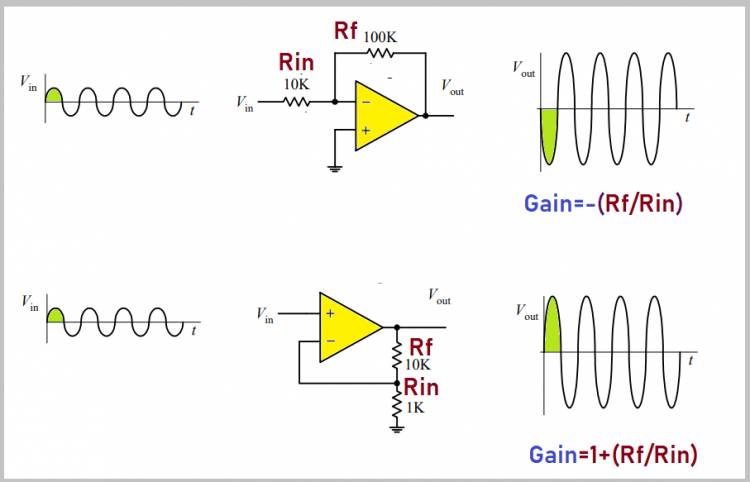
A non-inverting amplifier is a type of electronic circuit that amplifies the input signal using an opamp. In this circuit, the inverting input (inverting terminal) of the opamp is connected with ground, while its positive input (non-inverting terminal) is connected with the input signal. Non-inverting amplifier is used to amplify the input signal, usually at a positive rate, and transmit it to the output.
The gain of the non-inverting amplifier is calculated by the following formula:
Av = 1 + (Rf / Rin)
Here, Hunt is gain; Rf is the feedback resistance; and Rin is the input resistance. This circuit is used in applications such as audio amplification, amplifying sensor readings, and analog signal processing.
Inverting Amplifier:
An inverting amplifier is an opamp circuit that magnifies the input signal by reversing its phase. In this circuit, the positive input of the opamp is connected to ground, while its reverse input is connected to the input signal. An inverting amplifier is used to amplify the input signal, usually at a negative rate, to transmit it to the output, thus inverting the phase of the signal.
The gain of the inverting amplifier is calculated with the following formula:
Av = - (Rf/Rin)
Here, Hunt is gain; Rf is the feedback resistance; and Rin is the input resistance. This circuit is useful in areas such as signal processing, oscillatory circuits, and signal inverter applications.
Example applications may include audio amplification, biomedical devices, oscilloscopes, microphones, sensor interfaces and data processing systems. Both types of circuits are basic components widely used in the field of electronic engineering and circuit design.
Related Article: How to make an audio mixer with LM741?