Single Transistor FM Transmitter Circuit
This application is an FM transmitter application.
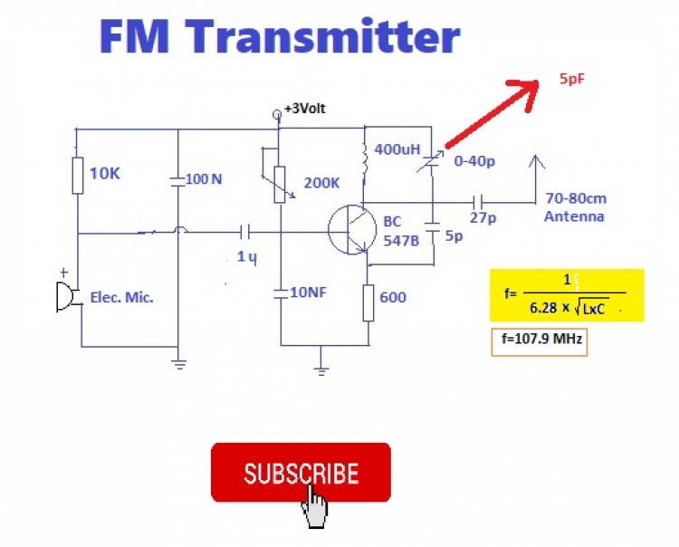
The FM transmitter works on the basis of frequency modulation. There is a frequency at which the LC circuit consisting of a coil and a capacitor connected to the collector leg of the BC547 transistor is in resonance. This frequency is the center frequency. According to the values in this application diagram (L=400nH, C=5pF), the center frequency is 107.9 MHz.
Visit our youtube channel:
The VCE voltage changes according to the analog level of the audio signal in the base circuit of the transistor, and this shifts the LC resonant frequency as well. Frequency changes occur just below and above the center frequency. This change is transmitted to the antenna via a 27pF capacitor. Thus, changes just below and above the center frequency begin to diffuse into the atmosphere.
Electret microphone was used as the microphone in the input part of the circuit. The 10K resistor protects this microphone from excessive current. According to the speech volume level, electrical signals are formed on the electret microphone. These signals are transmitted to the base of the BC547 transistor over a 1 microfarad capacitor.
There are many educational videos on Arduino, basic electronics and digital electronics on our channel.