Water Level Indicator Electronic Circuit
In this application we will use an NPN transistor. We will use the BC547 transistor, which we use in many laboratory applications, in this application as well.
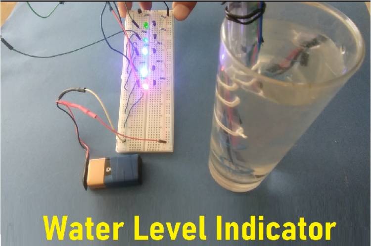
We built and ran our circuit on a breadboard. We have uploaded the relevant video to our Youtube channel.
First, let's get to know the BC547 transistor. The DC current gain of the BC547 transistor is 300. That is, if a base current of 1 micro ampere is supplied to this transistor, the current flowing through its collector will be a maximum of 300 micro amps. That would be 0.3 milliamperes.
It is mostly used as a switching transistor and as a signal amplifier in small signal applications.
The BC547 NPN transistor can also be used in low frequency systems. For example, an FM transmitter or FM receiver electronic circuit can be made, although it is not very powerful.
We have made FM transmitter circuit before.
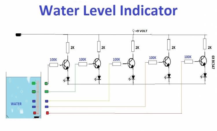
The name of the application we will do today is Water Level Indicator. In this circuit, we will use the transistor as the switching element. As you can see in the circuit diagram, when the base current is provided with a 100K resistor, the current flowing from the collector lights the LED. A 2K resistor is used to protect the LED from high current.
When the base end of the transistor and the +9 Volt ends of the circuit are immersed in water, the circuit is completed and the base current begins to flow. Hence, the collector current also starts to flow. If there is no water in the glass, the led will not light.