LoRa Technology
LoRa technology is a wireless communication technology that is used for long distance communication and does not depend on the internet. LoRa creates its own wireless network and can exchange data between devices without the need for an internet connection.
LoRa is long range wireless communication technology which stands for "Long Range". It stands out with its low power consumption and long range features. In this way, communication between devices can be carried out in a wide coverage area. LoRa is a frequently preferred technology especially in IoT (Internet of Things) applications, remote monitoring, sensor networks, smart cities, agricultural applications.
LoRa uses a proprietary protocol and typically uses unlicensed frequencies in the ISM (Industrial, Scientific, and Medical) bands. In this way, direct communication between devices can be achieved without internet addiction.
However, LoRa technology does not provide an independent internet connection. If devices need to provide access to the Internet, a separate connection method or connecting the LoRa network to a gateway may be required. In this way, it is possible to transmit data received from LoRa modules to the Internet.
LoRa technology has long communication ranges, typically between 2 and 10 kilometers. In addition, it has the ability to pass signals through obstacles. It usually operates in unlicensed ISM (Industrial, Scientific and Medical) bands such as 433 MHz, 868 MHz or 915 MHz. These frequencies offer low power consumption and wide coverage.
LoRa modules typically provide half-duplex communication. This means that they cannot be both a transmitter and a receiver at the same time. That is, they cannot send and receive data at the same time. However, it is possible for the module to operate as a receiver or transmitter at varying time intervals depending on the situation.
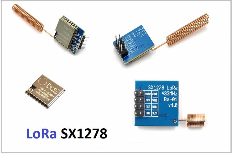
Today, LoRa modules can be easily integrated with microcontrollers. On our site, we share some microcontrollers and different modules' wiring diagrams and code examples. We have added the code samples below, which should be written after the Ra-01 LoRa SX1278 module we chose as an example is connected to the Arduino Nano.
Transmitter Connections:
Ra-01 DI0_PIN -> Arduino Nano D2
Ra-01 SCK_PIN -> Arduino Nano D13
Ra-01 MISO_PIN -> Arduino Nano D12
Ra-01 MOSI_PIN -> Arduino Nano D11
Ra-01 SS_PIN -> Arduino Nano D10
Ra-01 RST_PIN -> Arduino Nano D9
Receiver Connections:
Ra-01 DI0_PIN -> Arduino Nano D2
Ra-01 SCK_PIN -> Arduino Nano D13
Ra-01 MISO_PIN -> Arduino Nano D12
Ra-01 MOSI_PIN -> Arduino Nano D11
Ra-01 SS_PIN -> Arduino Nano D10
Ra-01 RST_PIN -> Arduino Nano D9
The codes required for two Ra-01 LoRa SX1278 modules connected to two Nanos to communicate with each other:
Transmitter Code (Transmitter):
#include <SPI.h>

#include <LoRa.h>
const int DI0_PIN = 2; // Connect Ra-01 DI0 pin to Arduino Nano D2 pin

const int SCK_PIN = 13; // Connect Ra-01 SCK pin to Arduino Nano D13 pin

const int MISO_PIN = 12; // Connect Ra-01 MISO pin to Arduino Nano D12 pin

const int MOSI_PIN = 11; // Connect Ra-01 MOSI pin to Arduino Nano D11 pin

const int NSS_PIN = 10; // Connect Ra-01 NSS pin to Arduino Nano D10 pin

const int RST_PIN = 9; // Connect Ra-01 RST pin to Arduino Nano D9 pin
void setup() {

   Serial.begin(9600);

   while (!Serial);
   LoRa.setPins(NSS_PIN, RST_PIN, DI0_PIN);

   SPI.begin(SCK_PIN, MISO_PIN, MOSI_PIN);
   if (!LoRa.begin(433E6)) {

     Serial.println("Failed to initialize LoRa. Check!");

     while(1);

   }
   Serial.println("LoRa transmitter started.");

}
void loop() {

   String data = "Hello, this is a LoRa test!";

   LoRa.beginPacket();

   LoRa.print(data);

   LoRa.endPacket();
   Serial.println("Data sent: " + data);

   delay(5000); // 5 second wait time

}
Receiver Code (Receiver):
#include <SPI.h>

#include <LoRa.h>
const int DI0_PIN = 2; // Connect Ra-01 DI0 pin to Arduino Nano D2 pin

const int SCK_PIN = 13; // Connect Ra-01 SCK pin to Arduino Nano D13 pin

const int MISO_PIN = 12; // Connect Ra-01 MISO pin to Arduino Nano D12 pin

const int MOSI_PIN = 11; // Connect Ra-01 MOSI pin to Arduino Nano D11 pin

const int NSS_PIN = 10; // Connect Ra-01 NSS pin to Arduino Nano D10 pin

const int RST_PIN = 9; // Connect Ra-01 RST pin to Arduino Nano D9 pin
void setup() {

   Serial.begin(9600);

   while (!Serial);
   LoRa.setPins(NSS_PIN, RST_PIN, DI0_PIN);

   SPI.begin(SCK_PIN, MISO_PIN, MOSI_PIN);
   if (!LoRa.begin(433E6)) {

     Serial.println("Failed to initialize LoRa. Check!");

     while(1);

   }
   Serial.println("LoRa receiver started.");

}
void loop() {

   if (LoRa.parsePacket()) {

     while (LoRa.available()) {

       String receivedData = LoRa.readString();

       Serial.println("Received data: " + receivedData);

     }

   }

}
These codes use the LoRa library and require SPI connectivity. The SS_PIN, RST_PIN, DI0_PIN,MOSI_PIN, MISO_PIN and SCK_PIN values indicate the pins of the LoRa module that are connected to the Arduino Nano. Power Supply must be configured correctly (3.3V and GND)
After uploading the code, the data sent by the transmitter Arduino Nano will be received by the receiving Arduino Nano and displayed on the serial monitor.
Before using the code, the LoRa library (LoRa.h) must be loaded on both Arduino Nanos. LoRa library can be found and loaded via "Library Manager" in Arduino IDE.
If it is desired to communicate on a different frequency, the following line should be changed:
if (!LoRa.begin(433E6)) : The value of 433E6 in this line indicates 433 Mhz. Other frequency options are:
For 868MHz: 868E6 (Ra-02)
For 915MHz: 915E6 (Ra-02)
Note:
While the LoRa Ra-01 module works in the 433 MHz frequency band, the LoRa Ra-02 module can operate in the 433 MHz, 868 MHz and 915 MHz frequency bands. The Ra-02 offers a wider frequency range, giving the user a choice.